Creating a graticule
|
Tool |
Tool set |
|
Graticule
|
GIS |

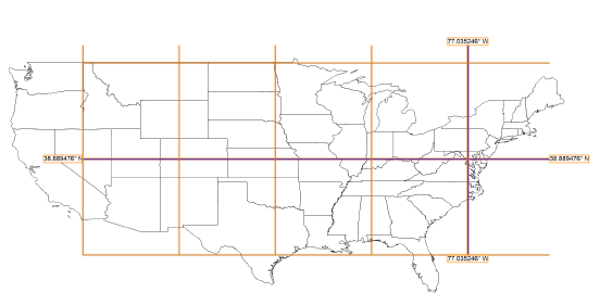
Use the Graticule tool to place a reference grid of real world parallels, meridians, and labels, showing the Earth’s orientation in a given area of the drawing. Unlike a grid that is based on X and Y coordinates, the graticule lines are based on longitude and latitude lines that are inferred from the georeferenced coordinate system.
The Document Georeferencing dialog box opens if the document is not yet georeferenced, to select a coordinate system. See Specifying document georeferencing.
![]()
|
Mode |
Description |
|
Draw Rectangular Area
|
Places the graticule grid in a rectangular area |
|
Draw Polylinear Area
|
Draws a polyline for the graticule area |
|
Polyline creation options |
For Draw Polylinear Area mode, selects the method for drawing the polyline upon which the object is based; see Polyline tool |
|
Preferences
|
Opens the Graticule Preferences dialog box to set the default preferences for graticules |


To create a graticule:
Click the tool and insertion mode, and then select the polyline creation mode.
Click Preferences to open the Graticule Preferences dialog box and specify the tool’s default parameters. The parameters can be edited later from the Object Info palette.
Click to show/hide the parameters.Click to show/hide the parameters.
|
Parameter |
Description |
|
Grid starts at |
Specifies the starting location for the grid spacing; the grid lines will intersect at this point |
|
Geodesic coordinates |
Specifies the starting location in longitude and latitude coordinates (decimal degree units) |
|
Cartesian coordinates |
Specifies the starting location in X and Y distances from the drawing’s internal origin |
|
Grid spacing |
|
|
Geodesic coordinates |
Specifies the grid spacing in longitude and latitude coordinates |
|
Cartesian coordinates |
Specifies the grid spacing in drawing distances |
|
Major lines at count |
Determines the spacing of major lines. For instance, if the value is 10, every tenth line will be major, with nine minor lines between them. |
|
Label |
|
|
Label major lines |
Places a label on each major latitude and longitude line |
|
Label grid lines |
Places a label on each minor latitude and longitude line |
|
Label style |
Specifies whether the degrees on the labels are in decimal or degrees/minutes format |
|
Label precision |
Sets the precision for the label display |
|
Attributes |
Specifies the pen color and line style for the major lines and grid lines |
Click and drag in the drawing to create the rectangular or polyline boundary in the approximate location of the latitude and longitude lines you specified. Make the area larger than the graticule will be, so the graticule will not be cut by the rectangle or polyline. When you complete the shape, a graticule object is created over the specified location.